Isometric Drawing on Graph Paper: Trade Drafting and Game Art
Most drawing systems trade accuracy for the look of depth. A perspective sketch tapers a receding edge to sell the illusion of distance, and once it does, a ruler is no longer any use on it -- the far end of that edge is not the length the drawing shows. Isometric projection makes the opposite trade. Foreshortening is dropped entirely, and in exchange, every edge that runs along one of the drawing's three axes -- straight up, and the two directions thirty degrees above horizontal -- is drawn at its true length, on the same scale as everything else on the page. That makes an isometric drawing closer to a measuring instrument than a picture, and it is why the grid turns up in three places that otherwise share nothing: a pipefitter's spool drawing, an assembly manual's exploded view, and a game engine's tile art. This article covers how the projection is put to work in trades this site has not covered before, where it diverges from the ratio most game engines actually use, and the mistakes that show up in all three.
One Grid, No Vanishing Point
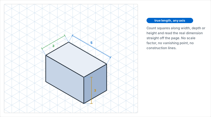
Isometric paper prints three families of lines instead of two: one vertical, and two running thirty degrees above horizontal in opposite directions. Every pair of those meets at a hundred and twenty degrees, so the grid has no privileged direction the way a square grid has "across" and "down" -- it has three axes, treated identically. Measure along any of them and the count of squares is the true, unforeshortened length, which is the entire point of the projection: a technical drawing that a reader can still take a dimension from without doing any construction first.
That is also the whole difference from perspective drawing, and it is worth being precise about, because the two get confused constantly. One-point and two-point perspective place a vanishing point and shrink everything as it recedes toward it, which is what makes a photograph-like drawing convincing and what makes it useless as a scale reference. Isometric projection has no vanishing point at all. Parallel edges in the object stay parallel on the page, and equal edges stay equal, no matter how far into the drawing they sit. Our guide to isometric graph paper walks through the basic construction step by step -- drawing the top face, dropping verticals, closing the sides -- and is the place to start if you have never built a cube on the grid before. This article assumes that part and goes to where the projection is actually put to work.
One technical note worth having before any of that: true isometric projection foreshortens all three axes equally, by a factor of about 0.816. Drafting practice ignores this on purpose. Because the foreshortening is identical on all three axes, an isometric drawing built at full scale -- one square counted as one unit, with no reduction applied -- is still internally proportional in every direction; it is simply about twenty-two percent larger overall than a mathematically exact projection would be. Nobody measuring a relationship between two features on the same drawing is affected by that, which is why isometric graph paper is printed and used at full scale rather than at 0.816 of it.
Piping and Process Isometrics
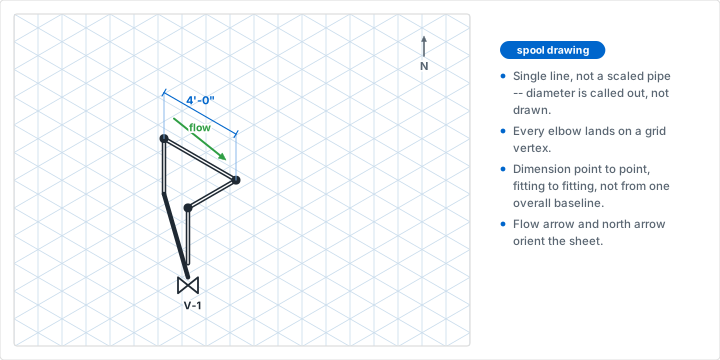
Long before piping design software existed, and still today for field markups and small jobs, pipefitters and plant designers drew pipe runs as isometric sketches called spool drawings. The convention survived because it solves a real problem: a pipe run turns in three dimensions, and across plan and elevation views alone, a reader has to piece that shape back together across two separate drawings and a great deal of cross-referencing. One isometric sketch shows the whole run's shape at once.
Reading a Spool Drawing
A spool drawing is a single-line drawing: the pipe is a line, not two lines representing its outside diameter, because the diameter is called out in a label rather than drawn to scale. An elbow is a corner where the line changes from one isometric axis to another, always landing on a grid vertex. A tee is a branch line leaving the run at a third axis. A flange is a short perpendicular tick across the pipe line; a valve is the bowtie symbol carried over from process and instrumentation diagrams. None of these symbols are drawn to scale either -- the drawing communicates connectivity and routing, and the fabrication dimensions live in the callouts beside it, the same division of labor a schematic uses for a circuit.
A flow arrow and a north arrow belong on every sheet. The flow arrow says which way the process fluid moves, which is not always obvious from the routing alone. The north arrow ties the isometric's orientation back to the plant's real coordinate system, so a fitter reading the sketch on site can relate "this elbow" to "that corner of the building" without re-deriving it.
Dimensioning Point to Point
Dimension a spool drawing between adjacent fittings, not from one overall baseline. Each length is the distance from the center of one fitting to the center of the next, and the run is built up as a chain of those, rather than as a series of measurements all taken from a single starting point. Chain dimensioning like this keeps an error local: get one length wrong and only the two fittings on either side of it are affected. Baseline dimensioning from one end of the run means every downstream length was measured against a point that might itself have drifted, and a mistake near the start throws off everything after it.
Exploded Assembly Views
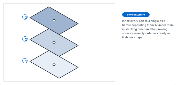
An exploded view answers a question an assembled drawing cannot: what order do these parts go together in, and what sits over what. The technique is to draw the assembly once, fully together, then pull every part away from its neighbors along a single axis -- almost always the vertical one -- while keeping each part's own shape and size exactly as drawn. Nothing about any individual part changes; only its position along that one axis moves.
Run a single dashed line through the center of every part before separating them, and index each part's position to it as you pull the stack apart. That centerline is what keeps an exploded view legible: a reader can follow it down through every part and see immediately which piece nests into which, even once they are spread a hand's width apart on the page. Number each part as you place it and collect the numbers into a simple parts list beside the drawing -- the same convention an assembly manual uses, because it works for the same reason there: a part identified by a number on a leader line does not have to be identified by shape.
This pairs directly with the isometric views our guide to woodworking plans covers for visualizing a finished piece. An orthographic plan gets you the dimensions; an assembled isometric view gets you the shape; an exploded isometric view gets you the order of operations, which is the one thing the other two do not show.
Packaging and Box Dielines
A dieline is the flat pattern a box folds up from: the panels, tabs, and glue flaps laid out on one sheet, with every fold and cut marked. It has to be drawn to real scale, because it becomes the cutting file, and it is one of the few isometric-adjacent jobs on this list where the flat pattern matters more than the 3D view. The isometric drawing's job here is secondary but still useful -- it is the sketch beside the dieline that shows how the flat panels actually close up, which is much easier to check by eye on a folded 3D sketch than by mentally folding a flat diagram.
Two line types carry the entire convention, and mixing them up is the one mistake that reaches a fabricator's cutting table. A solid line is a cut: the knife goes all the way through the board. A dashed line is a score: the board is creased, not cut, so the panel can fold along it without cracking. Tabs and glue flaps get their own shape, usually a shallow trapezoid so the flap tucks or glues without overlapping a fold it should not touch. Draw the box unfolded, in its flat state, at the same grid scale you will build the isometric preview from, and the two drawings will agree on every dimension without either one having to be re-measured against the other.
Isometric Game Art and Tile Design
Level designers and pixel artists reach for "isometric" constantly, and the word is doing two different jobs depending on who is using it. Our guides to designing video game levels and creating pixel art both touch on isometric grids for exactly this reason -- but the angle that reads as isometric on paper is not, in almost every case, the angle a game engine actually renders.
True Isometric Versus the 2:1 Game Tile
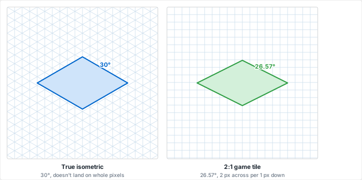
Paper isometric paper is drawn at thirty degrees, which is mathematically correct and looks right to the eye, but it does not tile cleanly on a raster grid. A thirty-degree line has a slope of about 0.577, an irrational-feeling ratio that lands a diagonal edge on a different fractional pixel every row, which is exactly the kind of edge that anti-aliases into a soft, blurry diagonal instead of a crisp one. Most software people call "isometric" tiles -- the classic look of city builders, dungeon crawlers, and strategy games going back decades -- are actually drawn at a 2:1 ratio instead: two pixels across for every one pixel down, an angle of about 26.57 degrees rather than 30. That ratio is technically a dimetric projection, not a true isometric one, and it exists purely because 2:1 is a clean integer relationship on a pixel grid, where 30 degrees is not.
This matters for how you use the paper, not whether you use it. True isometric graph paper is still the right surface for planning a scene's composition, silhouette, and layout -- the angle is close enough that decisions about what reads well hold up at either ratio. What does not carry over directly is tracing a 30-degree paper sketch onto a tile sheet at 1:1. Redraw the final asset at whatever ratio your engine actually uses, almost always 2:1, and treat the paper version as the plan rather than the template. The dungeon-crawler tile look in particular traces straight back to hand-drawn dungeon maps; our guide to drawing tabletop RPG maps covers the paper-and-pencil side of the same tradition.
Sizing a Sprite Footprint
A 2:1 tile's footprint is usually specified as a width and a half-height in pixels -- a 128 by 64 diamond is a common base tile size, with the object's height drawn straight up from that footprint in whatever the art style calls for. Sketch the footprint on paper first at a comfortable scale, a few squares to the diamond, and work out how tall a building, a tree, or a character needs to read at that footprint before committing to final pixel dimensions. It is much cheaper to redraw a paper sketch than a finished tile sheet.
Choosing Your Grid Size
| What you are drawing | Grid size | Why |
|---|---|---|
| Pipe spool sketches | 1/4 in or 5/8 in squares | Not to scale; coarse spacing keeps fittings and labels legible |
| Exploded assembly views | Match the orthographic plan's scale | Parts must stay true size before they are pulled apart |
| Packaging dielines | 1/8 in, or 5 mm metric | The flat pattern becomes the cutting file; scale has to be exact |
| Game tile concept sketches | Whatever is comfortable to draw at | Composition is the goal here, not final pixel dimensions |
| Product or engineering isometrics | 5 or 10 squares per inch | Matches the fine ruling of the orthographic views alongside it |
Whatever the job, print the sheet at 100 percent with page scaling off before drawing anything you intend to measure from. Our printing tips guide covers the driver settings that quietly rescale a page, and on a dieline or an assembly drawing a page printed a few percent small is not a small error -- it is a drawing that no longer agrees with the parts it describes.
Mistakes That Cost You a Drawing
Mistake: Letting Perspective Creep Back In
Problem: A far edge gets drawn slightly shorter than the matching near edge, out of habit from perspective sketching. The drawing looks fine at a glance and is no longer measurable -- two edges that should be equal length are not.
Solution: Keep every edge on the same axis the same printed length, full stop. If you are unsure what that looks like corrected, our isometric graph paper guide shows the two side by side.
Mistake: Tracing a 30-Degree Sketch Straight Onto a Tile Sheet
Problem: A paper isometric sketch is traced onto pixel art at 1:1, and the diagonal edges land on fractional pixels the whole way down, producing a soft, inconsistent stair-step instead of a clean diagonal.
Solution: Use the 30-degree sketch for planning composition only. Redraw the final asset at your engine's actual ratio, almost always 2:1, where the diagonal falls on whole pixels.
Mistake: No Common Centerline on an Exploded View
Problem: Parts are pulled apart by eye rather than along a marked axis, and they drift sideways as well as apart. The stacking order stops being obvious, which defeats the point of exploding the view in the first place.
Solution: Draw one dashed centerline first and index every part's position to it before separating anything.
Mistake: Cut Lines and Score Lines Drawn the Same Way
Problem: A dieline uses one line style for both cuts and folds, or the two are not labeled. A fabricator working from it has to guess, and a guessed score line becomes a cut.
Solution: Solid for cut, dashed for score, always, with a small key on the sheet for anyone seeing it for the first time.
Conclusion
Isometric drawing is not one technique wearing three costumes so much as one genuine property -- true length along three fixed axes, with no vanishing point -- that happens to solve three unrelated problems. A pipefitter needs a run's shape without piecing together plan and elevation views. An assembly needs its stacking order shown, not just its final form. A dieline needs to fold up the way the flat pattern promised. None of that requires trusting an angle by eye; it requires a grid ruled at exactly thirty degrees, which is what isometric paper is for.
The one place to stay alert is game and tile art, where "isometric" is often shorthand for a 2:1 dimetric ratio rather than the true thirty-degree projection the paper is ruled at. Use the paper for planning either way, and re-derive the final pixel ratio deliberately rather than tracing straight through.
Print Isometric Graph Paper
Set the grid style to isometric, choose your spacing, and print at 100 percent with scaling off. Free, with no account and nothing to install.
Create Isometric Graph PaperRelated Resources
- Isometric Graph Paper -- the grid this whole article runs on
- Engineering Graph Paper -- fine ruling for orthographic views alongside an isometric
- Woodworking and DIY Project Plans -- isometric views for visualizing a finished piece
- Sketching Circuits on Graph Paper -- another trade that draws to a fixed grid before building
- Designing Video Game Levels and Maps -- planning the scenes this article's tiles go into
- Creating Pixel Art on Graph Paper -- one square, one pixel, at whatever ratio you settle on
- How to Choose the Right Grid Size
- Professional Printing Tips -- printing at true scale for a drawing you intend to measure