Model Railroad Track Plans on Graph Paper: Scale, Curves and Clearances
Every published track plan was drawn for somebody else's room, somebody else's benchwork and somebody else's locomotives. Copied onto your own table it usually fails in one of four ways: the curves are tighter than your longest car will take, the plan is deeper than you can reach, the climb needs more running room than the table has, or the passing siding turns out to be shorter than the train. All four are arithmetic, and all four are easier to see on squares than in your head. This article covers choosing a drawing scale and printing the sheet for it, drawing the room before the benchwork, getting the minimum radius and the bench width right, reading a turnout's frog number straight off the grid, counting a grade as rise over run, and checking that the train you want to run actually fits.
Pick the Drawing Scale and Print the Sheet
A track plan has two scales in it, and mixing them up is the first mistake. Keep them separate on paper and the rest of the drawing stays honest.
The Train's Scale and the Drawing's Scale
The train's scale is the ratio between the model and the real thing. It never appears on the plan as a measurement, because the plan is drawn in the real inches of your table, not in scale feet.
| Scale | Ratio | Standard track gauge |
|---|---|---|
| N | 1:160 | 9 mm |
| HO | 1:87.1 | 16.5 mm |
| S | 1:64 | 7/8 in |
| O | 1:48 | 1.25 in |
It is worth converting once, to calibrate your expectations. A four foot wide table is about 350 scale feet across in HO and about 640 in N. Eight feet of length is roughly 700 scale feet in HO, which is a long siding and not a long railroad. That is why plans are about selection rather than compression: you are choosing which few hundred feet of railroad to model.
The drawing scale is the other one, and it is the number you write in the corner of the sheet: one square equals some whole number of real inches or feet. Pick it from two constraints. The whole benchwork has to fit inside the squares the sheet prints, and your minimum curve radius has to land on a whole number of squares, because a radius that falls between lines is a radius you will mismeasure.
Settings for Letter, Tabloid and Ledger
In the graph paper generator, choose the standard grid, imperial measurements, the paper size, and a grid size of 0.25 inches. The line under the preview reports the square count, and that count is what decides the drawing scale. With the default half inch margins the generator fills the sheet with whole squares only:
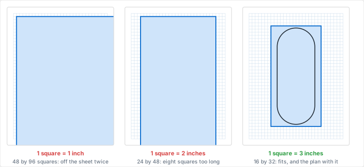
- Letter at 0.25 inches prints 30 squares across and 40 down. At one square to two inches that covers 60 by 80 inches, which is a shelf layout or a small island but not a four by eight foot sheet of plywood. At one square to three inches it covers 90 by 120 inches, and the four by eight fits as 16 by 32 squares.
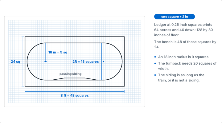
- Tabloid (11 by 17 inches) prints 40 across and 64 down, and Ledger is the same sheet turned landscape at 64 across and 40 down. At one square to two inches, Ledger covers 128 by 80 inches of floor, so a four by eight foot bench lands as 48 by 24 squares with sixteen squares of aisle to spare on each side. This is the sheet most plans want.
- Letter at one square to one foot prints 30 by 40 feet, which is bigger than most rooms. Use it for the room drawing rather than the track.
For a plan longer than one sheet, print two and tape them together along a grid line so the squares carry across the join, exactly as you would for any oversized drawing.
Metric on A4 and A3
Set the measurement system to metric, pick the paper, then set the grid unit to millimeters and the grid size last, because changing the grid unit resets the size. A4 at 10 mm squares inside 10 mm margins prints 19 squares across and 27 down. At one square to 100 mm that is 1.9 by 2.7 meters of baseboard, so a 1.2 by 2.4 meter board lands as 12 by 24 squares. A3 at the same settings prints 27 by 40, covering 2.7 by 4.0 meters.
Print Several and Work in Layers
Print at least half a dozen sheets. A track plan is not drawn once: the first version is thrown away, the second has the aisle in the wrong place, and the fourth is the one you build. Print at 100 percent with page scaling turned off, which the printing tips guide covers browser by browser, because a sheet shrunk to fit is a sheet whose squares are no longer the size you chose.
The alternative to redrawing is layering. Draw the room and the benchwork once in ink, then lay tracing paper over the sheet for each track arrangement. The grid shows through, so every version is drawn on the same squares and two of them can be compared by stacking. This is the same method the design sketching guide uses for product shapes, and it is faster than any amount of erasing.
Draw the Room, Then the Benchwork
Almost every layout that gets rebuilt was planned as a shape of benchwork rather than as a shape of room. Draw the room first, at one square to one foot, on its own sheet: walls, the door and the way it swings, windows, the furnace, the water heater, the breaker panel, the light switch, the floor drain and the ceiling slope if there is one. The same measuring routine as the room layout tutorial applies here, and the parts people forget are the same: record where each opening starts, not just how wide it is.
Then draw the benchwork on top of the room, and the aisles will draw themselves as what is left. A layout is the negative of its aisles, which is the opposite of how it feels while sketching ovals. Anything a plan takes from the aisle, you pay for on every operating session.
Aisles and Reach, Measured on Yourself
Two numbers govern the benchwork, and both are yours rather than a standard.
Your aisle. Stand sideways in a doorway with a tape and find the gap you can walk through without turning your shoulders. Plan on about 24 inches as the least you will tolerate, 30 where you will stand and work for an hour, and 36 where two people have to pass. At one square to one foot those are 2, 2.5 and 3 squares, so an aisle is easy to check: it is the empty strip between two drawn edges, and if it is thinner than two squares anywhere the plan has a pinch point.
Your reach. Stand at a kitchen counter and measure how far across it you can comfortably work with both hands. Most adults get somewhere near 30 inches, which is 15 squares at one square to two inches. A bench deeper than your own measured reach needs access from the other side, a removable section, or an opening in the scenery behind the track, because the track at the back will need re-railing, cleaning and repair for as long as the layout exists.
Mark the reach limit on the plan as a dashed line parallel to each bench edge. Any track beyond every dashed line is track you cannot get to, and seeing it drawn is more convincing than being told.
Minimum Radius Is a Number of Squares
Curve radius is where plans fail most often, and it is the easiest thing on the sheet to count. Radius is measured from the center of the curve to the centerline of the track, not to a rail, so draw the centerline and nothing else at this stage.
Take the number itself from your equipment rather than from an article. Sectional track is sold in named radii, printed on the box. Flex track lets you choose, in which case the limit is the minimum radius the makers publish for your longest locomotives and cars, usually in the specifications or on the box. Use the largest of those figures, not the average. Then add some: a broader curve looks better, because less of the car is visibly swung out from the track, and it is more forgiving of the small track faults every layout develops.
Convert once and work in squares from then on. At one square to two inches, every even radius in inches is a whole number of squares:
| Radius | Squares at 1 square to 2 in | Width of a half circle |
|---|---|---|
| 15 in | 7.5 | 30 in |
| 18 in | 9 | 36 in |
| 22 in | 11 | 44 in |
| 24 in | 12 | 48 in |
| 30 in | 15 | 60 in |
Draw the curve with a compass set to that many squares, pricking the center on a grid intersection so the radius can be checked by counting afterward. For a plan built around one big curve, polar graph paper is worth printing instead: set the ring spacing to 0.25 inches and every printed ring is two inches of radius at the drawing scale, so an 18 inch radius is the ninth ring out from the center. The radials give you the arc angles at the same time, 12 radials putting a line every 30 degrees.
Where a straight meets a curve, soften the join over a few squares by hand rather than running the compass arc straight into the tangent line. An eased entry both looks better and is kinder to long equipment, and on paper it costs an inch or two of the straight at each end, which is worth knowing before the straight is also a passing siding.
A Turnback Curve Sets the Bench Width
A half circle that brings the track back on itself is what decides how wide the benchwork has to be, and the arithmetic is short. The two centerlines are 2R apart. Beyond the outer centerline you need the overhang of your longest car, and beyond that whatever margin you want between the track and the edge of the bench so a derailed car stays on the table. Two inches a side covers both in the smaller scales.
So an 18 inch radius turnback needs about 40 inches of width and fits a four foot bench with room for scenery. A 22 inch radius needs about 48 and fits a four foot bench with nothing to spare on either side, which is the real reason so many plans settle on 18. In N, an 11 inch radius turnback needs about 26 inches and will not fit a two foot shelf, while a 9.75 inch radius needs about 24 and just does. Draw the half circle and the bench edge on the same squares and this decides itself in ten seconds.
Turnouts: The Frog Number Is a Slope
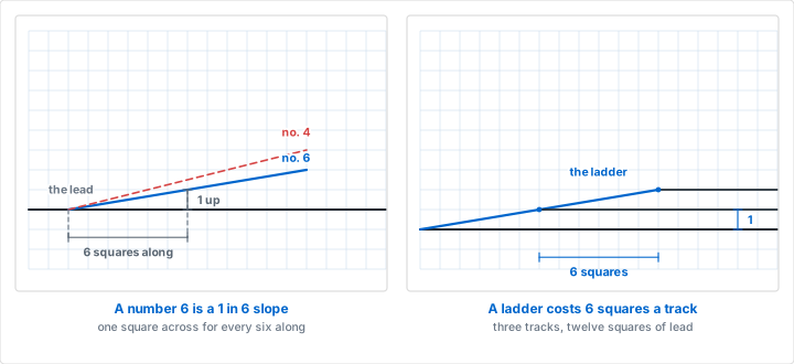
A turnout's number is its frog angle written as a ratio: a number 6 spreads one unit sideways for every six units along. That is a slope, which makes it the one piece of track geometry a grid draws perfectly. Beyond the frog, the diverging route is a straight line that leaves its neighbor by one square for every six squares along, at any drawing scale, because a ratio has no units.
Draw the diverging route that way and you get the right angle without a protractor. What the grid cannot give you is the overall length of the turnout, which varies between makers even at the same number. Take that from the maker's dimensioned drawing, or lay a real turnout on a sheet and trace around it to make a template you can reuse for the whole plan.
A Yard Ladder Costs Length per Track
The useful consequence is that a ladder of turnouts has a price per track, and it is a multiplication. If your tracks are C apart on centers and your turnouts are number N, each additional track pushes the ladder N times C further along:
- Number 6 turnouts with two inch centers: 12 inches of length per track, which is 6 squares at one square to two inches.
- Number 4 turnouts with the same centers: 8 inches per track, which is 4 squares.
- Number 8 turnouts with the same centers: 16 inches per track, 8 squares.
Reaching the fifth track of a yard off a number 6 ladder therefore spends about 48 inches, four feet, plus the length of the last turnout, before a single car is parked on it. Count that on the sheet before drawing the yard tracks, because a yard whose ladder eats half the bench is the most common way an eight foot plan ends up holding four cars a track. Shorter turnouts buy length back, at the cost of looks and of what long equipment will take through the diverging route.
Track Centers and Clearances
Two parallel tracks need enough space between them that two trains can pass, and the figure is not something to estimate. The National Model Railroad Association publishes recommended practice tables for track center spacing and for the clearance an obstacle needs beside the track, broken down by scale, by radius and by era of equipment, and they are free to read at the association's standards index. Look up your own scale rather than carrying a number across from someone else's.
Graph Paper Generator is independent and is not affiliated with, sponsored by or endorsed by the National Model Railroad Association. The name is used here only to identify where those tables come from.
Two things about spacing are worth holding in mind while you draw. The first is that a working figure for HO straight track is commonly two inches between centers, which is exactly one square at one square to two inches, so parallel tracks on a plan drawn at that scale are one square apart and need no measuring at all. The second is that curves need more, because a long car's ends swing outward through a curve and its middle swings inward, so two cars that clear each other on a straight can touch on a curve of the same spacing. The published tables give the widening by radius. If you prefer to verify rather than trust, set your two longest cars nose to nose on a curve of your minimum radius and look.
Clearances beside and above the track matter just as much, and are easier to forget because the plan is flat. Mark on the plan every tunnel portal, bridge abutment, signal, platform edge and scenery wall that will stand near the track, and write its distance from the centerline beside it in squares. A retaining wall drawn as a line on a plan is a solid object at the layout, and the car that hits it will be the long one.
Grades: Rise Over Run, Counted in Squares
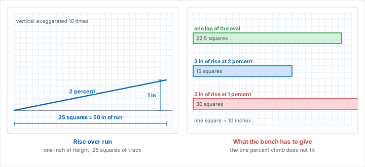
A grade is rise divided by run, written as a percent. Turn it around and it becomes the only grade question a plan has to answer: how far must the track travel to climb what it needs to climb? The run is the rise divided by the grade, so at two percent every inch of height costs 50 inches of track, which is 25 squares at one square to two inches. At three percent it costs about 33 inches, and at one percent a full 100.
That arithmetic is what makes a track crossing over itself an expensive idea on a small layout. Add up the vertical separation you need, which is the clearance figure for your scale plus the thickness of the roadbed and subroadbed carrying the upper track. Suppose it comes to three inches. At two percent the climb needs 150 inches of running track, twelve and a half feet, which is 75 squares. On a four by eight foot bench a simple lap around an 18 inch radius oval is about 225 inches, nineteen feet, so the climb takes two thirds of the lap and has to begin the moment the track has passed under itself. Draw the climbing section as a heavier line and count its squares. If the count comes out short, the choices are a steeper grade, a longer route, a lower crossing, or no crossing.
Mark the start and end of every grade on the plan with a short cross line and the height above the base at that point. Then check two things. A grade should not begin in a curve if it can be helped, because a train feels the two together and pulls worse than either alone predicts. And a grade and a turnout in the same place make a coupling that uncouples itself, so keep the turnouts on the level sections.
How Much Train Fits
The last check is the one that changes plans most and gets done least: measure the train, not the track. A scale 50 foot boxcar is 50 feet divided by the scale ratio, which is 6.9 inches in HO and 3.75 inches in N. So a 50 foot locomotive, ten 50 foot cars and a 40 foot caboose comes to roughly 81 inches in HO, which is 6 feet 9 inches, and that is before the turnout and the clearance point at each end of the siding. The same train in N is about 44 inches.
Draw it. At one square to two inches that HO train is a bar 41 squares long, and laying it on the plan settles several arguments at once: whether the passing siding holds it, whether the yard tracks hold half of it, whether it fits between the two turnouts of the crossover, and whether it is still inside the tunnel when the locomotive comes out the other end. Cut a paper strip to that length and move it around the plan the way you would move furniture cutouts around a floor plan.
If the train does not fit, shorten the train. A plan drawn for a six car train on a four by eight bench runs well, and a plan drawn for a twenty car train on the same bench runs badly at every single session.
Choosing Your Settings
| What you are drawing | Paper and grid | Drawing scale |
|---|---|---|
| The room, with doors and obstructions | Letter, 1/4 in standard grid | 1 square to 1 ft, 30 by 40 ft |
| A four by eight foot bench, whole | Ledger, 1/4 in standard grid | 1 square to 2 in, 48 by 24 squares |
| A shelf or switching layout | Letter, 1/4 in standard grid | 1 square to 2 in, 60 by 80 in |
| A yard throat or turnout cluster | Letter, 1/4 in standard grid | 1 square to 1 in, 30 by 40 in |
| A long plan you count in fives | Engineering, heavy every 5 | 1 square to 2 in, heavy line every 10 in |
| A single large curve | Polar, 1/4 in rings, 12 radials | 1 ring to 2 in of radius |
| A metric baseboard | A4 or A3, 10 mm standard grid | 1 square to 100 mm |
| A clean plan to keep or share | Dot grid, 1/4 in | Same scale, no lines to erase around |
Engineering paper earns its place on a long plan: a heavy line every fifth square means a 20 square run is four heavy intervals rather than twenty squares to count, and a miscount is the usual source of a bench leg drawn two inches from where it goes. The heavy lines start at the margin, so the first one falls on the left and top edges of the printed grid.
Mistakes That Ruin a Track Plan
Mistake: A Radius Chosen to Fit the Bench
Problem: The plan is drawn first and the curves are squeezed until they fit the table. The layout is then built, and the long locomotive the whole railroad was bought for will not go around the end.
Solution: Take the minimum radius from your longest equipment before drawing anything, convert it to squares, and draw the two turnback curves first. If they do not fit, the bench is too narrow or the equipment is too long, and that is a decision to make on paper.
Mistake: Benchwork Drawn Before the Room
Problem: A handsome plan arrives at the basement and the door opens into it, or the furnace needs a service clearance exactly where the yard goes, or the only aisle is 18 inches wide at one corner.
Solution: Draw the room at one square to one foot, with every obstruction and the door swing, then draw the benchwork inside it. Check every aisle is at least two squares wide along its whole length.
Mistake: Reaching for Track You Cannot Reach
Problem: A bench four feet deep against a wall looks generous on paper. In use, the back twelve inches collect derailments that can only be cleared by climbing onto the layout.
Solution: Measure your own reach, draw it as a dashed line inside each accessible edge, and keep track out of the gap between the dashed lines. Where depth is unavoidable, draw the access hatch or the removable section into the plan rather than promising to add one later.
Mistake: A Grade With Nowhere to Climb
Problem: The plan has one track crossing over another, and the crossing is drawn before anyone counts the run. Built, the grade comes out at five or six percent, and half the locomotives slip on it with four cars behind them.
Solution: Divide the vertical separation by the grade you are willing to accept, convert the answer to squares, and measure the climbing route on the plan. If the squares are not there, the crossing is not there either.
Conclusion
A printed grid turns a track plan from a drawing into a count. The radius is a number of squares, the aisle is a gap of squares, the ladder is so many squares per track, the climb is rise divided by grade and then counted, and the train is a paper strip of a known length. Nothing in that list needs a calculator, and every item on it is a mistake you would otherwise find after the plywood was cut.
Draw the room, draw the benchwork inside it, draw the two turnback curves at your real minimum radius, then let everything else fill the space that is left. The same squares that hold a woodworking plan for the benchwork will hold the railroad that sits on it, and if you want to see the finished scene standing up rather than flat, isometric paper and the methods in our isometric drawing article will take the same plan into three dimensions. Work in pencil, keep the rejected versions, and write the drawing scale in the corner of every sheet.
Print a Track Plan Grid
Quarter inch squares on Ledger: 64 across and 40 down, which is one square to two inches over a four by eight foot bench. Free, with no account and nothing to install.
Create Your Track Plan GridRelated Resources
- Room Layout Planning: measuring a room and drawing it to scale, which is step one of any layout
- Woodworking Plans on Graph Paper: drawing the benchwork itself, with cut lists counted in squares
- The Grid Method for Drawing: enlarging the finished plan onto the plywood square by square
- Engineering Graph Paper: heavy lines every fifth square for counting a long plan
- Polar Graph Paper: rings and radials for laying out a single large curve
- Design Sketching on Graph Paper: working versions of a design in layers over one grid
- Isometric Drawing: taking a flat plan into three dimensions
- Tabletop RPG Maps: another plan where one square stands for a fixed real distance